Coffee mills
 First design
 |
|
 Second design
|
The first design
For this design the base for the mechanism is made so that it will fit over a sutiable container which will receive the ground coffee. The container could be a ready made items such as a saucer or a small plastic basin, or it could be turned out of wood to a suitable form.
Material
A blank 5 inches in diameter and 3.5 inches thick is required. I used ash for my mills but I think almost any hard wood would be suitable.
Step 1
 |
|
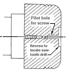
Attach the blank to a screw chuck and shape the outside as shown opposite. If you are going to drill the hole for the mechanism with a sawtooth drill cut a recess 1.5 inches in diameter as shown. This will make it easier to locate the drill in the centre of the piece. Not everyone will have a 1.5 inch drill so an alternative method of forming the hole will be described below in step 3. Sand and finish. Drill a pilot hole for the for the screw and reverse on the screw chuck ready for step two. |
Step 2
 |
|
Note that if the screw is over long a packing piece may be required so that the inside can be hollowed out without fouling the screw. The depth of the hollow will be determined by the length of the screws supplied with the mechanism. The hollowing is done with a bowl gouge followed by a scraper. The inside is then sanded and finished and the piece is taken off the chuck. If you have sawtooth drill the hole can now be drilled on the drill press. |
Step 3
 |
|
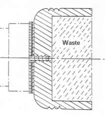
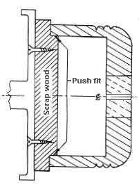
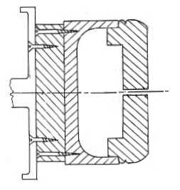
If a suitable drill is not available the hole for the mechanism can be formed by turning with a mall skew scraper making light cuts. Firstly, a piece of scrap wood is attached to a faceplate or a chuck and turned away to accept the base as a snug fit as shown. If you fail to get a good fit it may be possible to use some paper packing. It may also be useful to wrap some masking tape around both the scrap wood and the base to help hold it in place. The hole can now be cut. The scraper is eased into the wood at the side of the hole made for the screw. It will not be possible to go all the way through so a series of cuts are made working out from the centre to the required diameter. This series of cuts is repeated until all the waste has been removed. |
Step 4
The final step is to drill the holes for the fixing bolts and attach the mechanism.
The second design
For this design the base for the mechanism is made in the form of a box.
Material
Blanks required:
Top - 5 inches in diameter by 1.5 inches thick.
Bottom - 5 inches in daimeter by 2 inches thick.
Step 1

|
|
Mount the blank for the top with the bottom facing out using a packing piece if necessary. Turn it to the round and round off the top corner as much as possible. As this will be the finished size ensure that it will not be too big for the base. Cut the flange, which will fit into the bottom of the box, to the dimensions shown opposite. Make sure that the edges of the flange form a perfect cylinder (or as near perfect as possible); otherwise it will be difficult to get a good fit between the top and the bottom of the box at a later stage. Now hollow out the centre. The depth will be determined by the length of the screws supplied with the mechanism and the width must slightly larger than the pitch circle diameter of the fixing holes. For decoration a bead can be formed on the corner above the flange. Sand and finish the inside and remove from the chuck.
|
Step 2
Mount the blank for the base on the screw chuck bottom outwards and rough it to the round. At this stage its diameter should be slightly greater than that of the lid. Turn the base flat and then, if you will be using a chuck with expanding jaws, cut the required recess. If you will be turning the base on a faceplate then cut a small recess as shown in the diagram in step 3. Remove from the chuck.
Step 3
 |
|
Either mount the base on a chuck or, if you will be using a faceplate, proceed as follows. Mount a piece of scrap wood on a faceplate, clean off the face and then turn a spigot to fit the recess in the bottom of the base that you formed in step 2. The reason for this procedure is to ensure that the work piece is centred correctly. Then glue the base to the scrap wood applying the glue only around the edge of the base. Do not glue the spigot into the base. This will make it easier to remove the scrap wood at a later stage.
Now begin the the removal of the waste. Take care in the later stages not to remove too much material as the shaping of the top will will be done with it fitted to the base. Ideally, to do this the top should be a snug fit. When fitting the top make sure that the wall on the upper part of the opening is cylindrical in form. If this is not done then the base and the lid may not fit together properly. Give the hollow round 'corners' at the bottom to make it easier to clean.
|
Step 4
 |
|
The final shaping to the top is done with it in place on the base. Ideally to do this the top should be a snug fit on the base. Try not to make the fit too tight or you may have problems removing the top later. If you should make it too loose then it may be possible to pack it out with paper. With the top in position clean off the upper face and round off the corners. Then turn the sides of the base to align with the top. Remove the lid and add a bead to the lip of the base if required. A small amount of material should now be reoved from the inside of the lip on the base so that the top can be removed easily.Sand and finish the base. Take the base, together with the scrapwood, off the lathe. |
Step 5

|
|
Mount another piece of scrap wood on the face plate and turn it away to accept the base as a snug fit. Now turn off the scrap wood attached to the base.
The final step is to drill the holes for the fixing bolts and attach the mechanism.
|
|